Hello World, How to Mill Printed Circuit Boards (PCB)
This post is part of the Hello World Projects.
There are many ways to create custom PCBs (printed circuit boards). I like milling because the CNC mill can etch the traces, drill the through-holes, and cut the board all with one machine. All in a few minutes if your board is small.
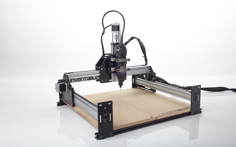
My friendly neighborhood SoDo MakerSpace has a Shapeoko 2, which I've been using. In this tutorial, I'll show you how mill some PCBs.
Credit for the original version of this tutorial goes to ähöüokul on Instructables, and thanks to Alex Cheker for pointing me to it. Now, on with the show!
Ingredients
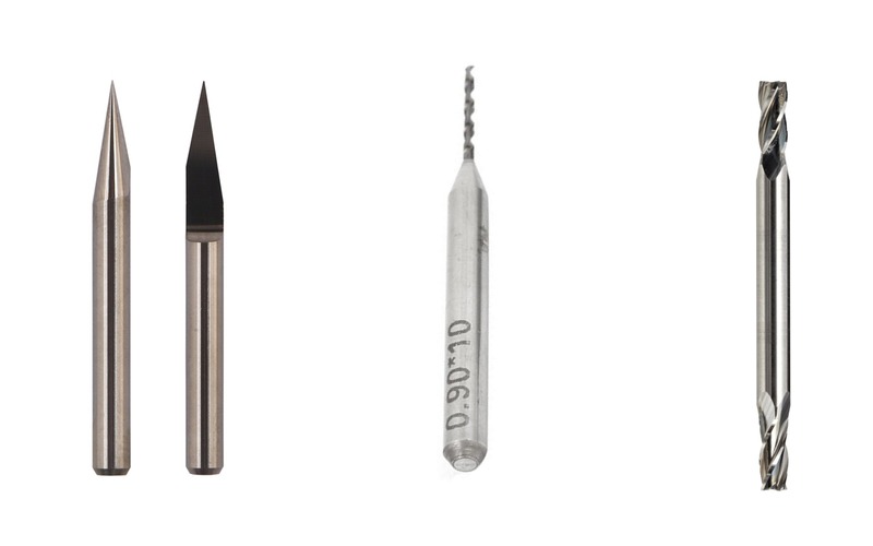
Software Hardware- Engraving Bit (20o, 0.2mm)
- Drill Bit (0.9mm)
- Square Nose Endmill (1/16 inch)
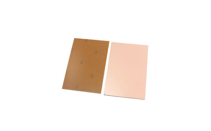
- Copper FR1 Boards , NOT FR4!!
- Shapeoko 2 running on GRBL
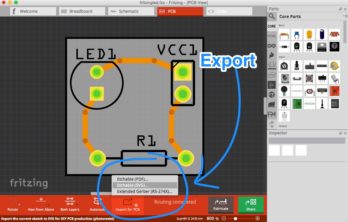
Step 1: Export to SVG
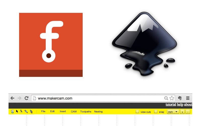
In Fritzing:- Export SVG:
Export PCB > Etchable SVG
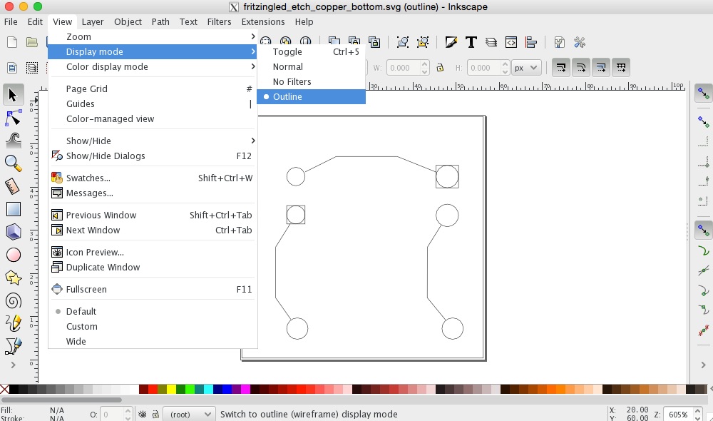
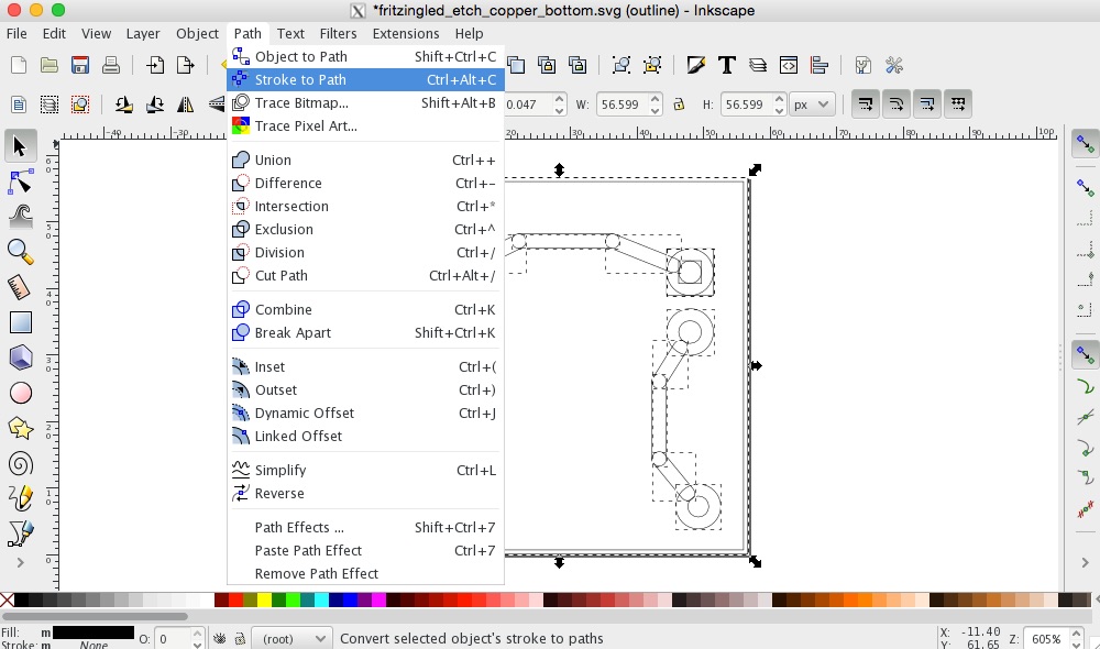
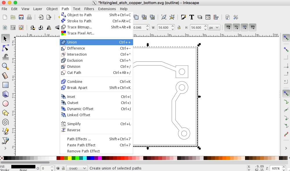
Step 2: Process SVG with InkScape
- Open InkScape (download )
filename either xx_etch_copper_top.svg or xx_etch_copepr_bottom.svg - [Optional]
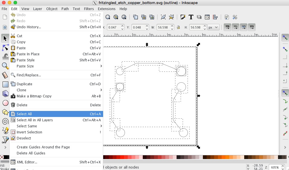
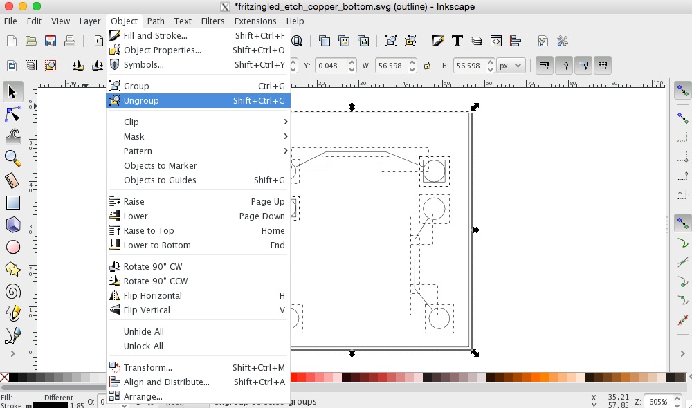
View > Outline Edit > Select All (Ctrl+A) Object > Ungroup (Ctrl+Shift+G) , repeat until you see "No groups to ungroup" in the bottom
Step 3: Open SVG with MakerCam
- Go to makercam.com
- Open SVG:
File > Open SVG
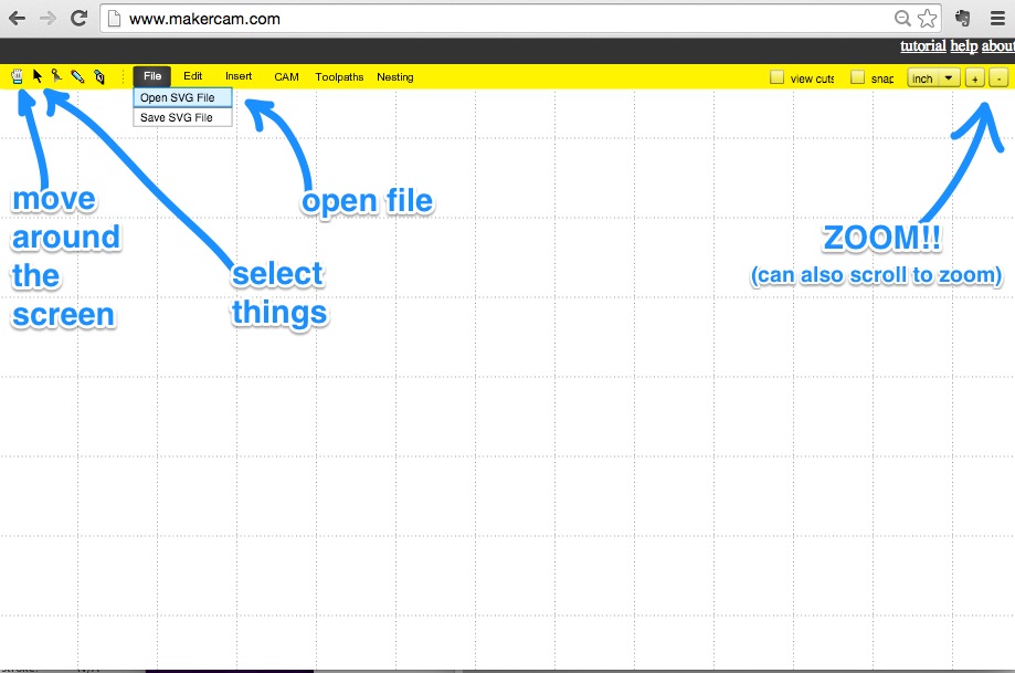
Some Navigation Tips
- To Pan:
Toolbar > Hand Icon - To Zoom:
Toolbar > Plus/Minus Icon or Scroll Up/Down - To Select:
Toolbar > Arrow Icon , then click or click+drag to select
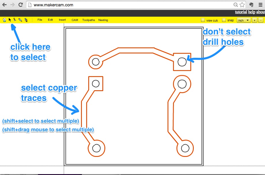
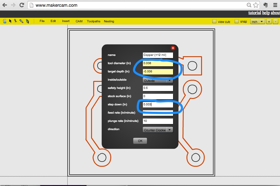
Step 3: Make Copper Trace
- Select copper trace outlines
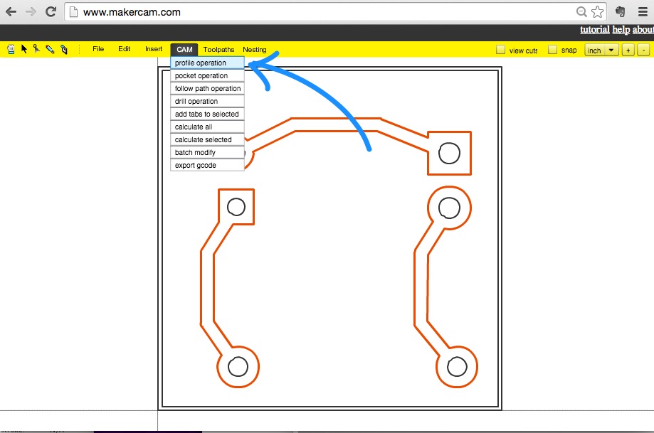
- Create Profile
CAM > Profile
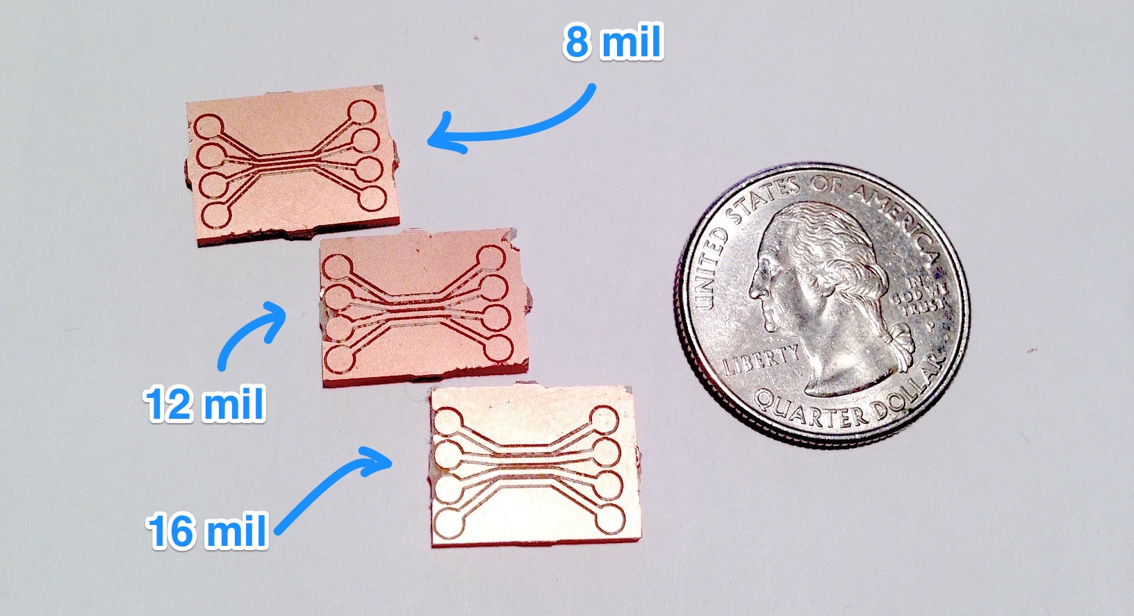
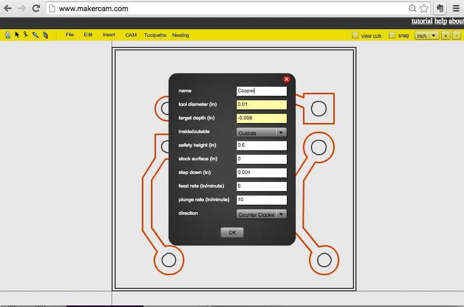
| Profile for Traces | > 12 mil | < 12 mil |
|---|---|---|
| tool diameter (in) | 0.01 | 0.008 |
| target depth (in) | -0.008 | -0.006 |
| inside/outside | Outside | |
| safety height (in) | 0.5
| |
| stock surface (in) | 0 | |
| step down (in) | 0.004 | 0.003 |
| feedrate (in/min) | 6 | |
| plunge rate (in/min) | 10 | |
| direction | counter clockwise | |
Tool: Engraving Bit (20 deg, 0.2mm)
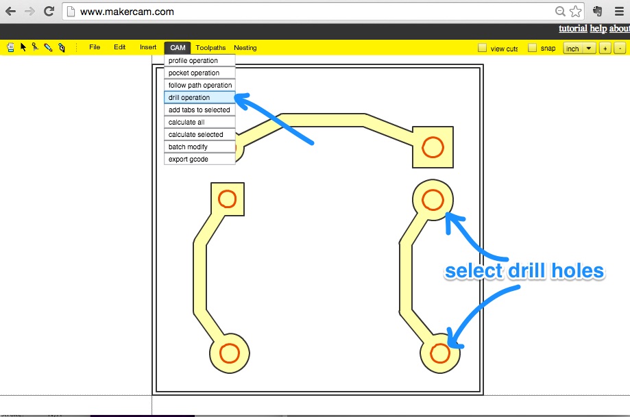
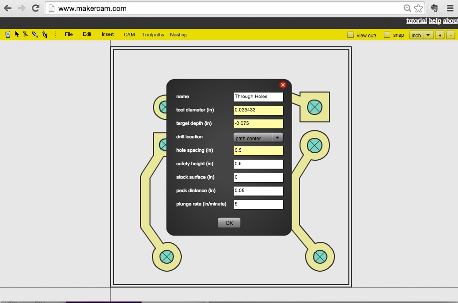
Step 4: Make Through Hole
- Select through hole outlines
- Create Profile:
CAM > Drill Operation
| Through Hole Profile: | |
|---|---|
| tool diameter (in) | 0.035433 |
| target depth (in) | -0.075 |
| drill location | path center |
| hole spacing (in) | 0.5 |
| safety height (in) | 0.5 |
| stock surface (in) | 0 |
| peck distance (in) | 0.05 |
| plunge rate (in/min) | 5 |
Tool: Drill Bit (0.9mm)
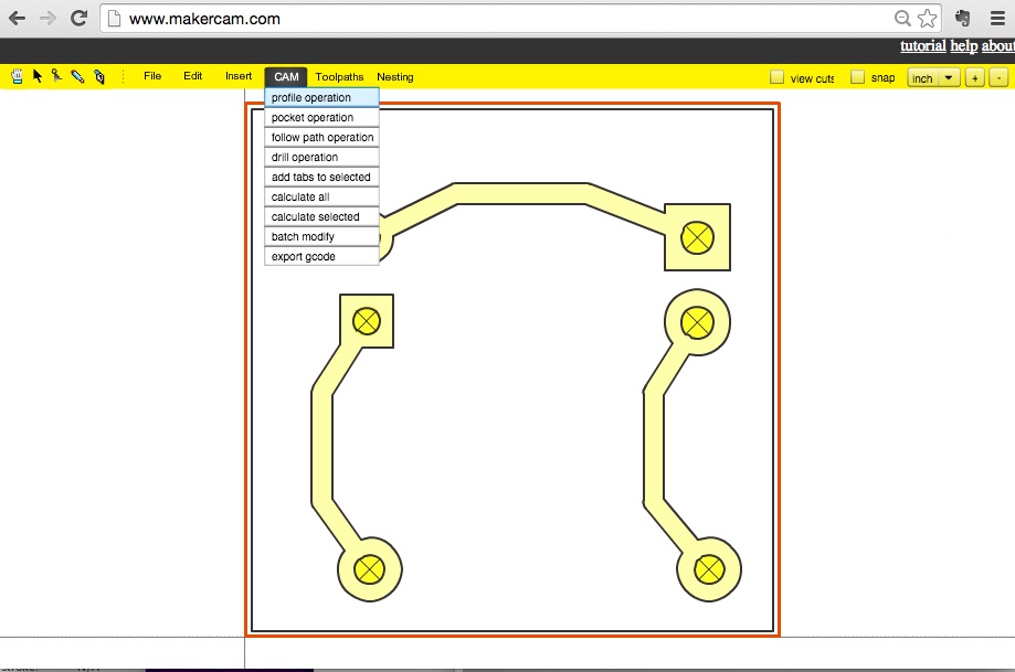
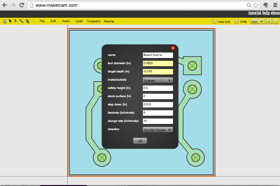
Step 5: Make Board Outline
- Select board outlines
- Create Profile:
CAM > Profile Operation
| Board Outline Cut Profile: | |
|---|---|
| tool diameter (in) | 0.0625 |
| target depth (in) | -0.075 |
| inside/outside | Outside |
| safety height (in) | 0.5 |
| stock surface (in) | 0 |
| step down (in) | 0.015 |
| feed rate (in/minute) | 6 |
| plunge rate (in/minute) | 10 |
| direction | Counter Clockwise |
Tool: Square Endmill (1/16 in)
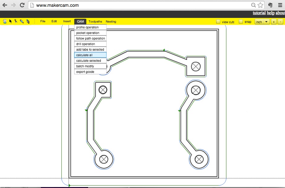
Step 6: Calculate GCode
Cam > Calculate All
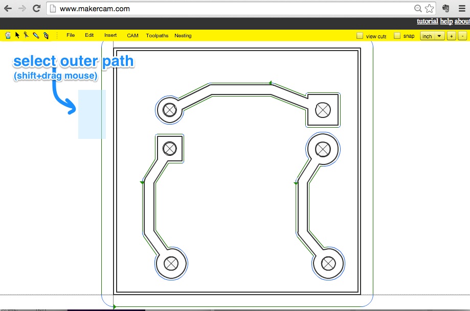
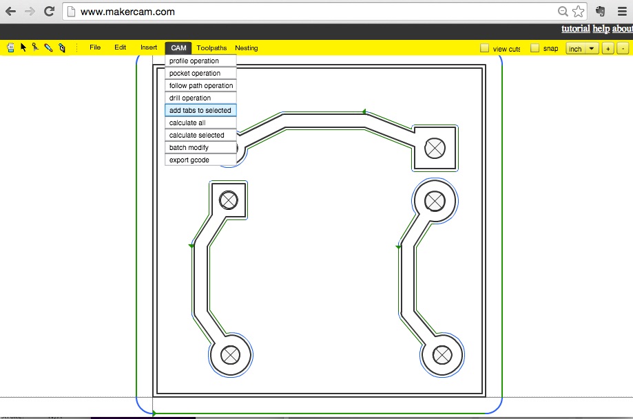
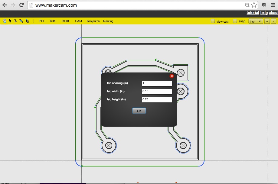
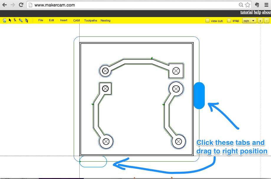
Step 7: Add Tabs
- Select Board Outline Path
- Add Tabs:
CAM > Add Tab to Selected
| Tab Settings | ||||||||||||||||||||||||||||||||||||||||||||||||||||||||||||||||||||||||||||||||||||||||||||||||||
|---|---|---|---|---|---|---|---|---|---|---|---|---|---|---|---|---|---|---|---|---|---|---|---|---|---|---|---|---|---|---|---|---|---|---|---|---|---|---|---|---|---|---|---|---|---|---|---|---|---|---|---|---|---|---|---|---|---|---|---|---|---|---|---|---|---|---|---|---|---|---|---|---|---|---|---|---|---|---|---|---|---|---|---|---|---|---|---|---|---|---|---|---|---|---|---|---|---|---|
| tab spacing (in) | 1 | |||||||||||||||||||||||||||||||||||||||||||||||||||||||||||||||||||||||||||||||||||||||||||||||||
| tab width (in) | 0.15 | |||||||||||||||||||||||||||||||||||||||||||||||||||||||||||||||||||||||||||||||||||||||||||||||||
| tab height (in) | 0.25 | |||||||||||||||||||||||||||||||||||||||||||||||||||||||||||||||||||||||||||||||||||||||||||||||||
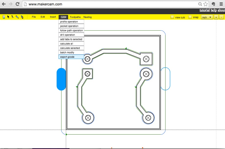
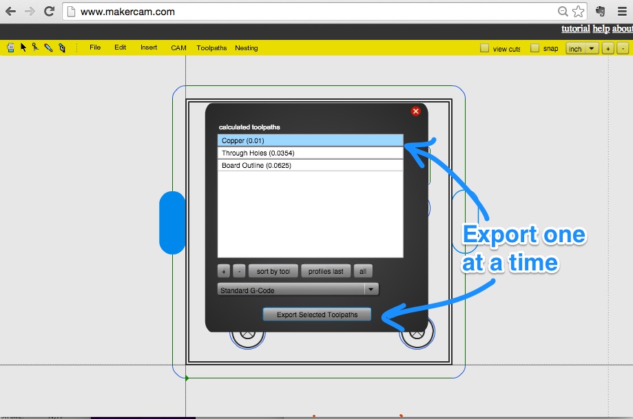
Step 8: Export GCode
Cam > Export GCode - Select one path at a time
- Click "Export Selected Toolpath"
| Tools to use during CNC | ||||||||||||||||||||||||||||||||||||||||||||||||||||||||||||||||||||||||||||||||||||||||||||||||||
|---|---|---|---|---|---|---|---|---|---|---|---|---|---|---|---|---|---|---|---|---|---|---|---|---|---|---|---|---|---|---|---|---|---|---|---|---|---|---|---|---|---|---|---|---|---|---|---|---|---|---|---|---|---|---|---|---|---|---|---|---|---|---|---|---|---|---|---|---|---|---|---|---|---|---|---|---|---|---|---|---|---|---|---|---|---|---|---|---|---|---|---|---|---|---|---|---|---|---|
| traces | engraving bit (20 deg, 0.2mm) | |||||||||||||||||||||||||||||||||||||||||||||||||||||||||||||||||||||||||||||||||||||||||||||||||
| holes | drill bit (0.9 mm) | |||||||||||||||||||||||||||||||||||||||||||||||||||||||||||||||||||||||||||||||||||||||||||||||||
| board | square endmill (1/16 in) | |||||||||||||||||||||||||||||||||||||||||||||||||||||||||||||||||||||||||||||||||||||||||||||||||
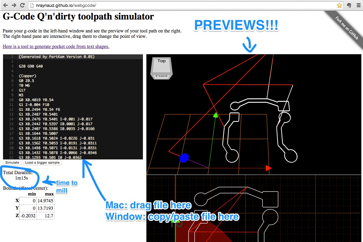
Check Your Code
- Go to: G-Code Q'n'dirty Simulator
- Copy/Paste the GCode (.nc) text data into left box
- Click Simulate Button
Bloop bloop!
Cut it OUT!
Step 9: Mill It!
- Clamp board in
- Turn Shapeoko On
- Unlock GRBL Controller
- Click
Choose File button - Bring Engraving Bit to touch the surface of the board
- Click the "Start" button
Repeat for through holes (w/ drill bit), then the board cut (w/ endmill)

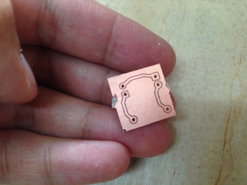
Step 10: Snap the Tabs
Snap and you're set!I've managed to get some super fine boards with this method. Check out this Intel Edison breakout board I did
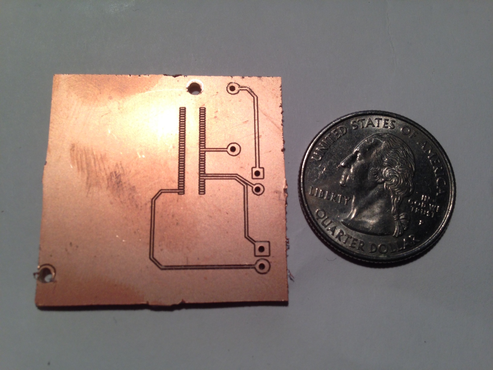
It's so pretty!
Got it? Got it. Now go make things.