PCBs Misbehaving
I got my custom PCBs from iTEAD last week. So exciting, right?
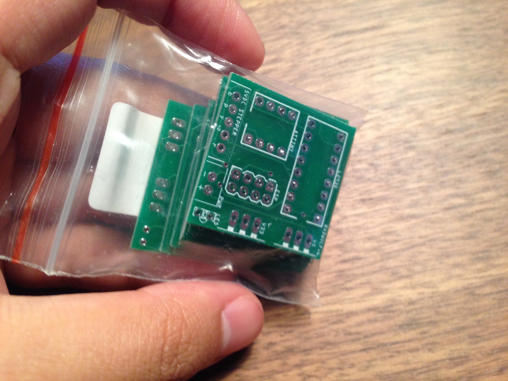
I plugged everything in and.... WARHN warhn (failure horn 📢).

Problem
So much trouble trying to figure out what's the issue. The LED would sometimes turn on, sometimes it wouldn't, sometimes the LED would turn on and stay on. I think this indicated that the ESP8266 was frozen. The motor would work maybe 10% of the time. And it was all completely random. I checked my soldering for loose connections. Resoldered a few suspicious (but I think they were fine) connections. Poke and prodded this little green thing with my multimeter.
Root Cause (I think? Maybe?)
I suspect it's had something to do with my 5V Regulator. It seems to be working off a lot of heat. I didn't have a heat sink for it. Trying to debug it let me all over the place. Sometimes it would give me a steady 5V (or 4.9V), other times it would putt along at a 4.2V. I suspect this might be because my 9V battery was losing too much juice too quickly. The 5V Regulator I used (7805 TO-220) needs a minimum of 7V to output a consistent 5V, according to Adafruit product description. So 4.2V output is no go since the L293D motor driver has a minimum supply voltage of 4.5V (and a max of 36!) so that was a no go.
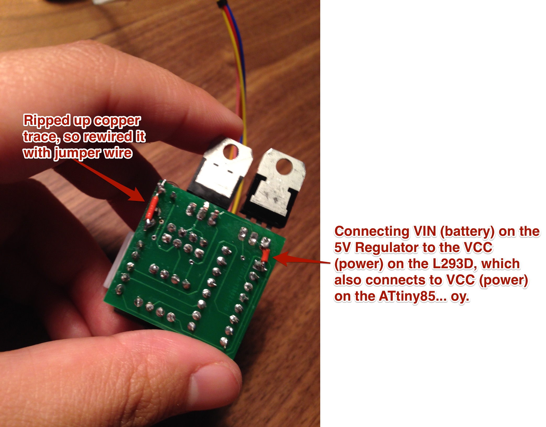
The other problem was my LED. I got some LED that came with built in resistors, but I think when I soldered them in I soldered them above where the resistor were. So I had to redo the LED. I used a handy white LED the second time since white LEDs have the highest forward voltage. I ended up tearing up the copper traces during this "fix" and had to solder in wires manually (see pic below).
Solution (ish)
To solve the 5V Regulator problem I decided to just F it and use a different battery pack. I got out my handy 4 AA battery. This starts at a 6V and works its way down to a 4.4V. With a fresh set of batteries it's a little too high for the ATtiny85 chip, which has a max supply voltage of 5.5V. However, it doesn't stay at 6V for long and the batteries I'm using is definitely not at 6V. I then added a manual wire connection between the Input on the 5V regulator and the VCC on the L293D chip. Basically, I bypassed the 5V regulator and plugged the power source directly onto the ATtiny85 and L293D Motor Driver.
It's probably not the safest or the smartest thing to do. BUT IT WORKS! It's so beautiful it works. And it's tidy.
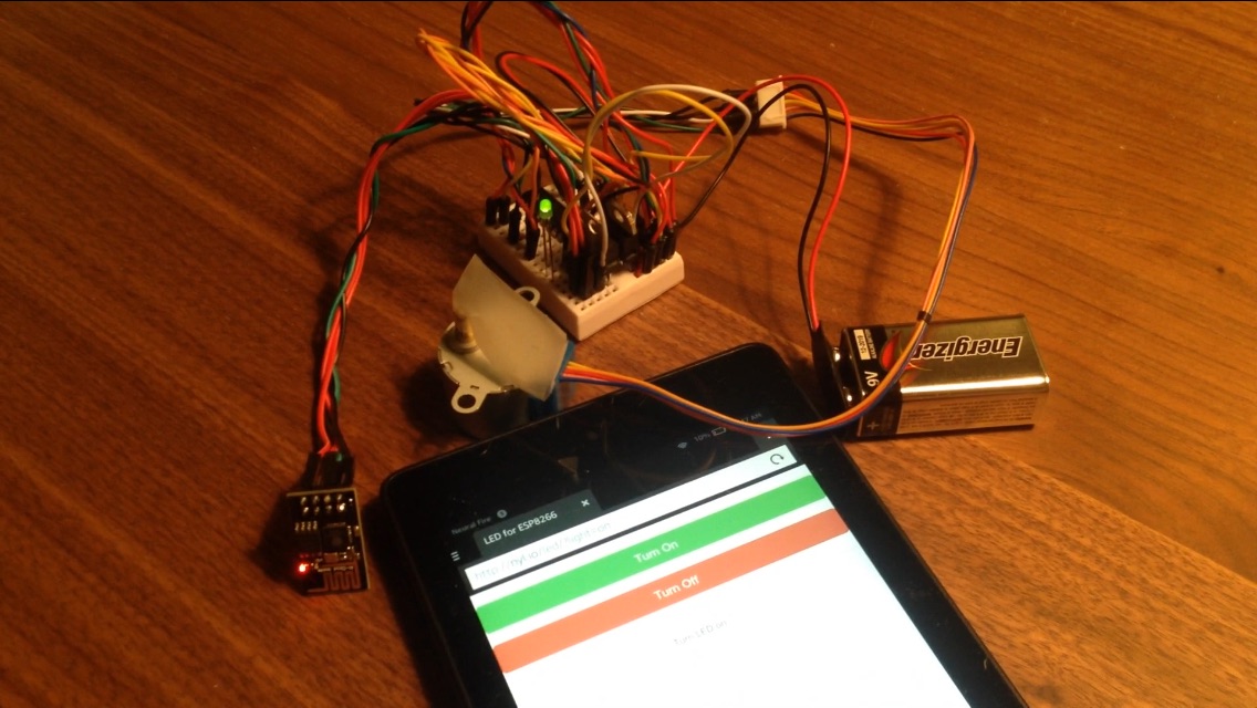
Before (breadboard):
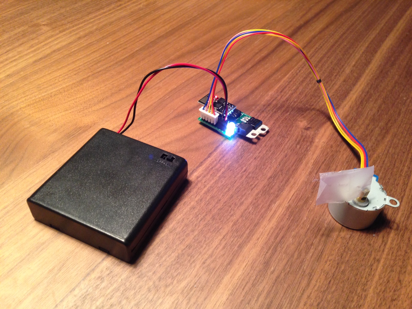
After (custom PCB):

So tidy. Much tiny.
Next Steps
To get these components in their comfortable range of operation, I'll try routing the ESP8266 (& LED) and ATtiny85 through a 3V Regulator and leave the L293D Motor Driver (& Stepper Motor) directly connected to the 9V Battery.
| Component | Min Supply Voltage | Max Supply Voltage | Current Power | Proposed Power |
|---|---|---|---|---|
| ESP8266 | 3.3V | 3.6V | 3V Regulator | |
| LED | 2.5V | 3.2V | ESP8266 (3.2 V on HIGH) | |
| ATtiny85 | 1.8V | 5.5V | 5V Regulator | 3V Regulator |
| L293D Motor Driver | 4.6V | 36V | 5V Regulator | Battery (4.4-9V) |
| Stepper Motor | 5V | 5V | L293D | |
Also Next Steps
Rather than waiting another two weeks to get a PCB, I'm researching how to etch my own PCB at home. It seems like a huge hassle, but I figure it's probably worth being able to rapidly prototyping board after board.
The problem is I'm woefully undersupply. I looked into it, and I'll need something like:
- Drill press (for the through holes and vias)
- Feric Chloride (sp?) for etching away the copper
- FR4 Copper Boards
- Safety stuff: gloves, goggles, work mask
- Laser printer (or more chemicals that I'll probably splash on things I shouldn't splash weird chemicals on. Like my dog)
- Some tool to cut the FR4 material
If I want to get fancy, I might need:
- Laminator
- A bunch of sheets that does fancy transfer things
Seems like a lot of stuff.
Is it worth it?