Wifi Controlled Motors using ESP8266 and ATtiny85
Picking up where we left off, I'm still on my way to create the cheap wifi connected, internet controlled motor. I think I found my perfect combination of awesome.

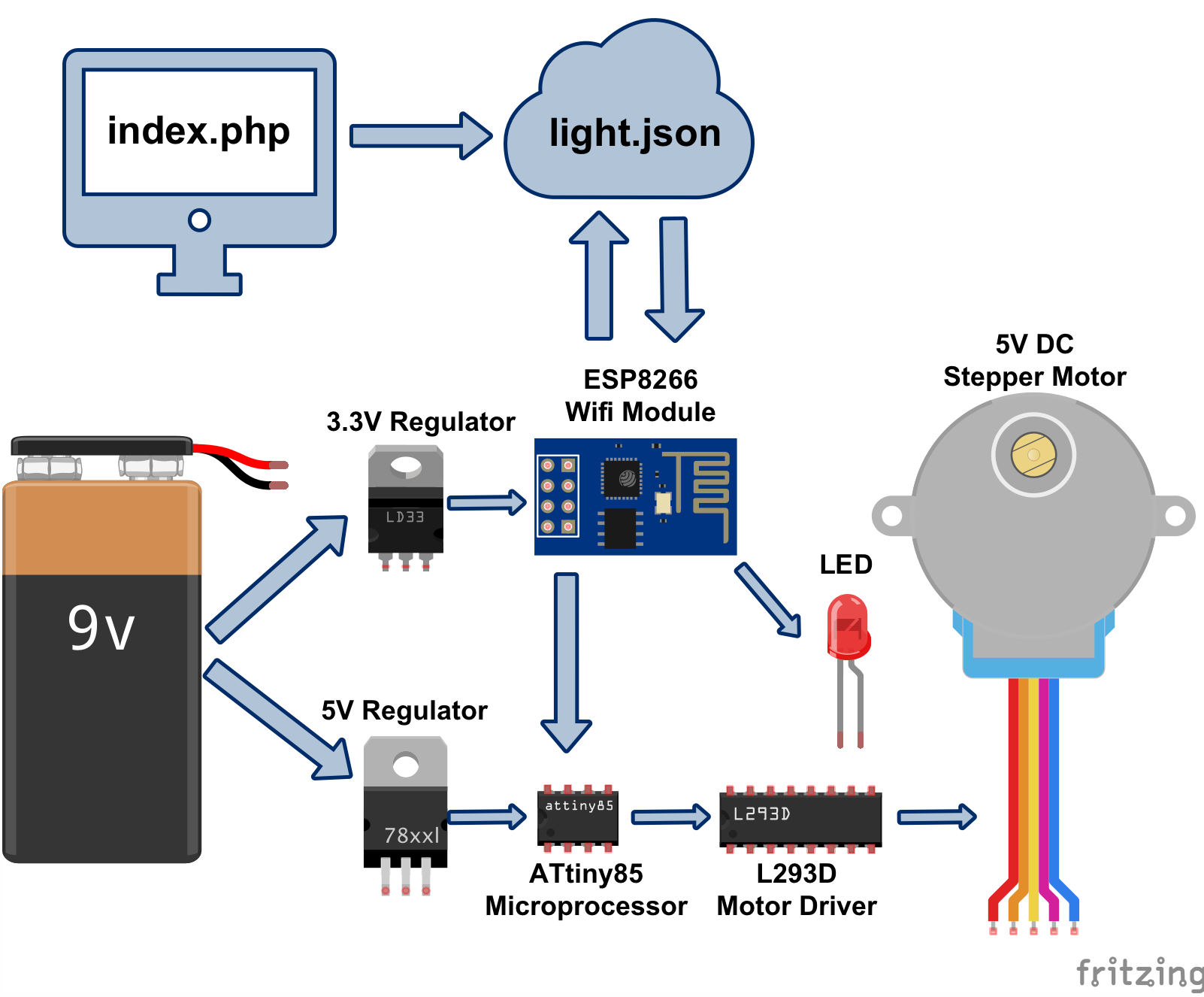
PLEASE NOTE: The ESP8266, index.php, and light.json part was covered the previous tutorial, which goes over how to program an ESP8266 with Arduino IDE, and hook it up to the internet. It also explains how the ESP8266 should ping light.json, and how index.php sends info to light.json. Again: here's the link to the previous tutorial!
And as always, you can find the code, diagrams, and all sorts of goodies on this project's GitHub Page.
Gather Ye, Ingredients
Main Components:
- ESP8266-01 Wifi Chip
- Arduino Uno for flashing the ATtiny85
- ATTiny85
- L293D Motor Driver
- 5VDC Stepper Motor
General Electronics
- 10uF Capacitor (link is to a bunch of assorted capacitors)
- LED This link comes with assorted LEDs and a pack of resistors to boot. For this project, use a purple or white light (closest to 3.3V). Or you know. Use resistors. You can also use LEDs with built in resistors to be safe.
- 3.3V Regulator
- 5V Regulator
- 9V Battery
- 9V Battery Connector
Step 1: Prep the Arduino Uno as an ISP
Before, I had whipped up this whole system with an Arduino controlling the motor instead of an ATtiny85 chip. I learned that you can actually flash some Arduino programs on the ATtiny85 chip, which is AWESOME. The ATtiny85 chip (the thing I'm holding here) is smaller and cheaper than the Arduino.
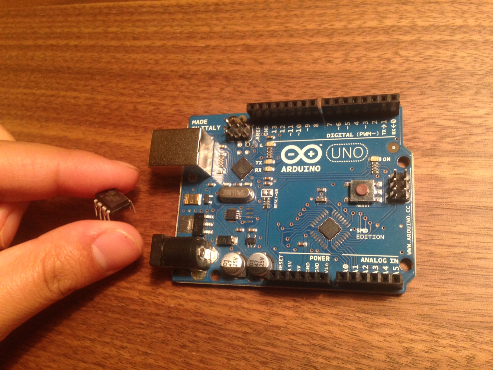
So adorbs, right?
Prepping the Arduino:
- Download the Arduino IDE if you haven't already
- Hook up the Arduino Uno to your computer using a printer cable
- Open up the ArduinoISP sketch (File > Examples > ArduinoISP)
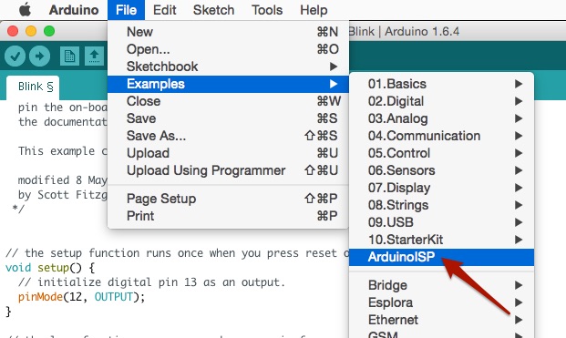
- Click "Upload" button (the right arrow above the code area)
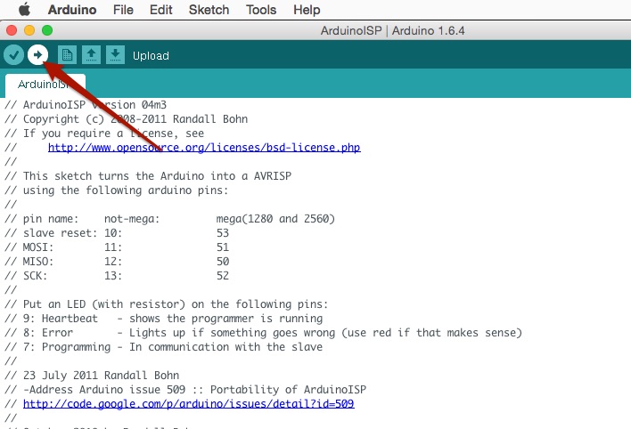
Then BAM! Your Arduino is now ready to program Atmel Chips!
Step 2: Add ATtiny85 to Arduino IDE
Now we're going to add ATtiny85 to the list of available boards. This way, you can use Arduino language to program ATtiny85.
-
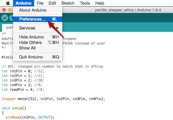
Go to: Arduino > Preferences
-
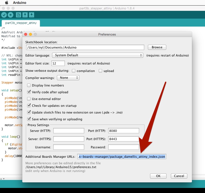
Add this to Additional Board Manager URLs at the bottom and click "OK" when done: https://raw.githubusercontent.com/damellis/attiny/ide-1.6.x-boards-manager/package_damellis_attiny_index.json
-
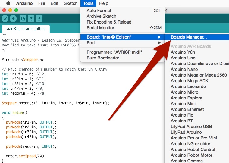
Go to: Tools > Board > Board Manager
-
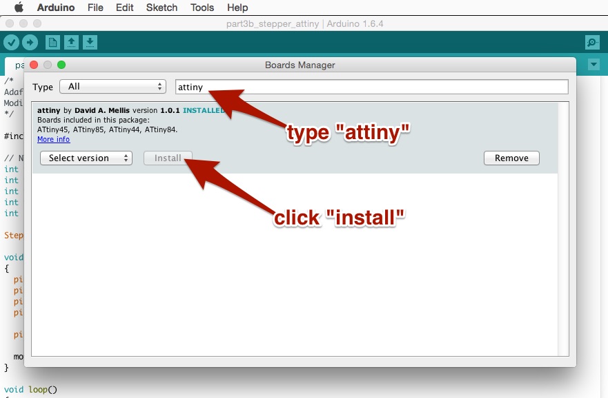
Search for "attiny," click on it, then click "install"
-
Restart Arduino
-
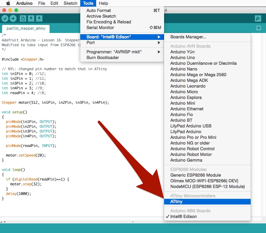
Go to: Tools > Board > ATtiny
Step 3: Wire it Up
Wire everything up like so. The Arduino IDE will send the code directly to ATtiny85. Please note the 10uF capacitor. This prevents the Arduino from resetting and starting up bootloader mode.
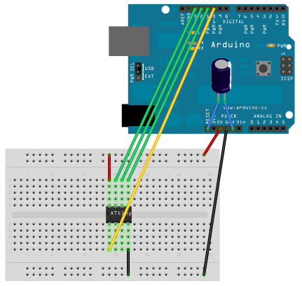
(image source: High Low Tech Blog)
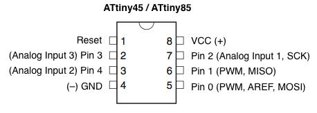
Here is the pin labels for the ATtiny85 (and ATtiny45)
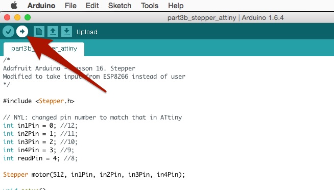
Step 4: Code for the ATtiny85
I based this off of Adafruit's Arduino/Stepper Motor Tutorial. I made a few tweaks to Adafruit's code. You'll see the changes in where I commented out the original values and why.
Go to: File > New and copy/paste the following code:
/*
Adafruit Arduino - Lesson 16. Stepper
Modified to take input from ESP8266 instead of user
*/

#include <Stepper.h>

// NYL: changed the following 4 lines to match ATtiny85's pin number
int in1Pin = 0; // was 12
int in2Pin = 1; // was 11
int in3Pin = 2; // was 10
int in4Pin = 3; // was 9
int readPin = 4; // NYL: new line, not in original Adafruit Tutorial

Stepper motor(512, in1Pin, in2Pin, in3Pin, in4Pin);

void setup()
{
  pinMode(in1Pin, OUTPUT);
  pinMode(in2Pin, OUTPUT);
  pinMode(in3Pin, OUTPUT);
  pinMode(in4Pin, OUTPUT);
  pinMode(readPin, INPUT);  // NYL: new line, listens for input on readPin

  motor.setSpeed(20);
}

// NYL: changed this to read input from ESP,
// then proceed at 32 steps every 1 second
void loop()
{
  if (digitalRead(readPin)==1) {
    motor.step(32);
  }
  delay(1000);
}
File > Save because you should always save your work!!
Step 5: Flash the ATtiny85
All righty! Your ISP (Arduino Uno) is ready. Your code is ready. Let's flash some ICs! 🎉🎉🎉
Go to "Tools" and select the following settings:
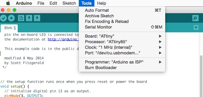
Just click "Upload" (the right arrow button).
There are some other tutorials on flashing the ATtiny85 you can look at if this doesn't work:
- High Low Tech Blog Posts (this one and that one) are great.
- There's also this post on Hackster that is pretty good.
Step 6: Hook Everything Up
Last I hooked everything up to get the motor running off of interwebs bits. I put some scotch tape on the motor so you can see it turning more easily.
Here's a cleaned up drawing of the wiring:
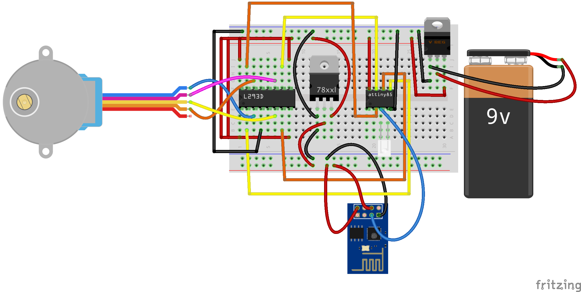
In this diagram, the top breadboard power track represents 5V, and the bottom represents 3.3V. The basic logic follows the diagram at the beginning of this blog post. Rather than conceptual arrows, we have wires and breadboards.
Now, if you go to your index.php page, you can click the "Light On" and "Light Off" button. Only now, the light and the motor should turn on.
OOOOO... fancy.
Next Steps
Just when you think you've shrunken everything, there's a way to get things even smaller. For me, the next step is to make a Custom PCB of this and get rid of all the wires and breadboard.
After that, I might even start looking into getting the surface mount version of it working, so it's even smaller (and cheaper). At this point, the battery and the motor will be the biggest pieces. So if you guys know of smaller 5V battery and motors, [drop me a line!](mailto: _@nyl.io) ✉️
Ok. Now go make stuff.